

Start node
The Start node is the mandatory first node in any workflow. It defines the input data model and passes this data to subsequent nodes.Use Workflow Data Models to define structured input and output parameters at the workflow level. Input parameters automatically pre-fill the Start Node from the data model.
External triggers
SaaS · 5.12Available on SaaS with FlowX.AI 5.12. This feature is live on managed (SaaS) deployments now. Self-hosted deployments will receive it with the next LTS release family.
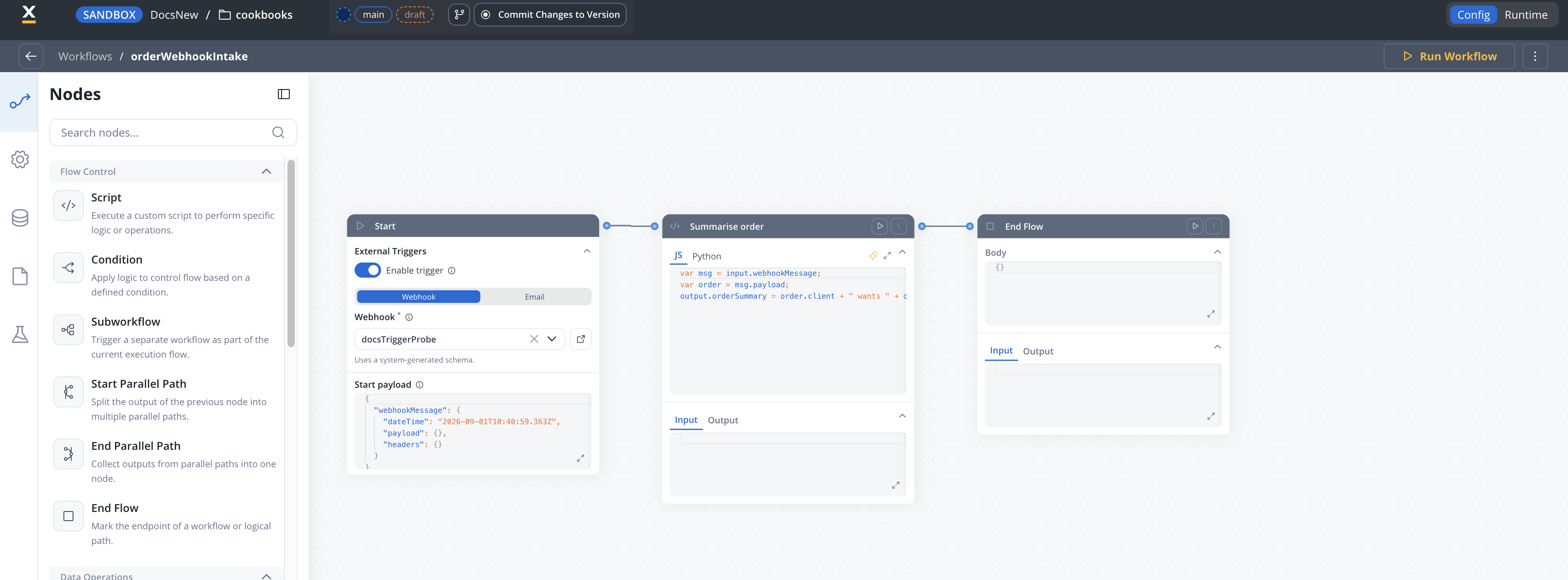
External triggers are available on Output Focused workflows only. Configuring one on another workflow type is rejected.
To run a workflow on a schedule on SaaS, add a schedule to its Start node. See How do I run a workflow on a schedule?. Self-hosted deployments get workflow schedules with the next LTS release. Until then, create a process with a Timer Start Event and call the workflow from it with a Start Integration Workflow action. See Scheduled processes.
payload holds the request body as sent, nested structure intact. headers holds each header as a list of strings, so a single-valued header still arrives as a one-element list.
A script node can then read it directly:
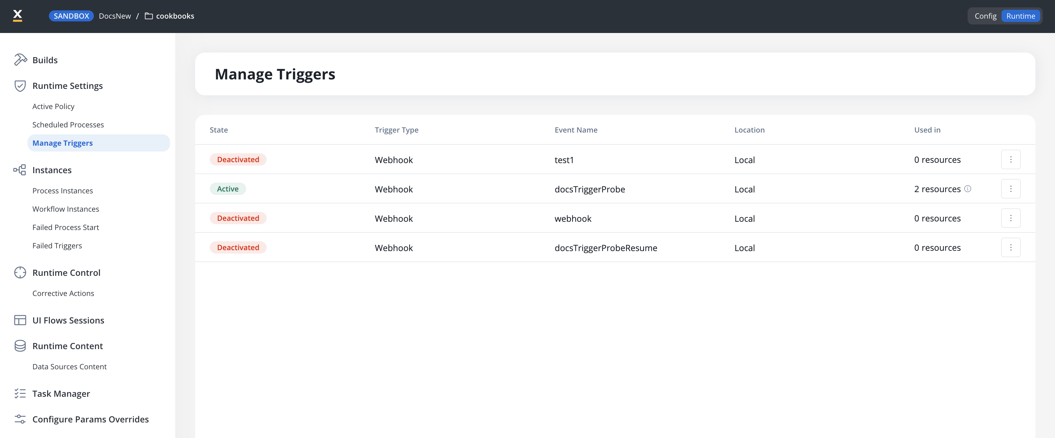
Incoming webhooks
Creating a webhook data source, Webhook Behavior, providers, the URL and its API key
Email trigger
Creating an email trigger data source, filtering, polling, and the email data schema
How do I run a workflow on a schedule?
SaaS · 6.0Available on SaaS with FlowX.AI 6.0. This feature is live on managed (SaaS) deployments now. Self-hosted deployments will receive it with the next LTS release family.
1
Add a schedule
Open the Start node, expand Schedules, and click Add schedule. Click the new schedule card to open the Schedule Workflow dialog, and give the schedule a Name.
2
Set when it fires
Choose a Timer Type:
- Date fires once, at the Fire at date and time, entered in your local time.
- Cycle fires repeatedly. Pick a Format, ISO or Cron, then build the expression with Guided fields or type it under Expression.
3
Activate the schedule
Go to Runtime → Runtime Settings → Schedules, filter Origin by Workflow, and click Activate on the schedule. The workflow must be part of the project’s active build.
What does a scheduled run receive? A scheduled run doesn’t use the Start node’s test payload. Its input holds three fields that you can map like any other input:
Where do scheduled runs show up? In Workflow Instances, with the origin Schedule. The run details name the schedule that started it.
How do I stop a schedule? To pause it, click Deactivate on the Schedules page, and click Activate to resume it. To remove it for good, delete it from its card on the Start node. A deleted schedule stops firing immediately, and the deletion can’t be undone.
REST API Call node
Enables communication with external systems via REST API calls. Supports GET, POST, PUT, PATCH, and DELETE methods. Endpoints are selected from a dropdown, grouped by system.- Params: Configure path, query, and header parameters.
- Input/Output: Input is auto-populated from the previous node; output displays the API response.
When does a REST API Call node take its failure exit?
A REST API Call node has a success exit and a failure exit. It takes the success exit only for a2xx response without errors. Everything else takes the failure exit:
- a non-
2xxresponse; - a timeout, stored as status
408withdata.timeout: true(set the limit with Timeout on the node’s Settings tab, default10000ms); - a connection error;
- a response body declared as JSON or XML that can’t be parsed.
408, 429, 500, 502, 503, or 504 is retried first, and the node takes the failure exit only once the retries are used up.
On both exits the node writes its result under its response key: data (the parsed body), metadata (statusCode and headers), hasError and errorMessage. hasError only flags connection and parsing errors: a 4xx or 5xx with a readable body has hasError: false even though the node took the failure exit, and on a timeout it isn’t set. To branch on the outcome, use the exits or metadata.statusCode, not hasError.
Errors while building the request, such as a failed input mapping or a missing endpoint, don’t use the failure exit. They fail the workflow instance.
FlowX database node
Allows you to read and write data to the FlowX Database within your workflow.FlowX Database Documentation
Learn more about FlowX Database operations, collections, and usage
Condition (Fork) node
Evaluates logical conditions (JavaScript or Python) to direct workflow execution along different branches.- If/Else: Routes based on condition evaluation.
- One branch per run: The node follows the first branch whose condition passes, or the Else branch. To run branches at the same time, use the Start Parallel and End Parallel nodes.
Use fork nodes to implement business rules, error handling, or multi-path logic.
Available bindings
Condition expressions have access to the following data bindings:Condition examples
- JavaScript
- Python
Calling reusable functions in conditions
SaaS · 5.11Available on SaaS with FlowX.AI 5.11. This feature is live on managed (SaaS) deployments now. Self-hosted deployments will receive it with the next LTS release family.
- JavaScript
- Python
Start Parallel and End Parallel nodes
Run several steps of a workflow at the same time with a pair of nodes: Start Parallel splits the flow into branches that all run at once, and End Parallel waits for every branch, merges what the branches wrote, and continues. In the node palette they sit under Flow Control as Start Parallel Path and End Parallel Path. Dropped on the canvas, they are named Start Parallel and End Parallel. These nodes are the only way to run branches concurrently. A Condition (Fork) node evaluates its conditions and follows one branch.How do I run steps in parallel?
1
Add a Start Parallel node
Drag Start Parallel Path from the Flow Control group onto the canvas and connect the previous node to it.
2
Create one sequence per branch
Draw a sequence from the Start Parallel node to the first node of each branch. Every outgoing sequence is a branch. A branch needs at least one node: the Designer does not let you connect a Start Parallel node straight to an End Parallel or End Flow node.
3
Build each branch
Add the nodes each branch needs: REST endpoints, scripts, FlowX Database operations, AI nodes, subworkflows, or another Start Parallel node for nested branches.
4
Close every branch on the same End Parallel node
Connect the last node of every branch to one End Parallel Path node, then connect that node to whatever comes next. An End Parallel node allows a single outgoing sequence.
What data does each branch see?
Each branch starts with a deep copy of the workflow data as it was when the Start Parallel node ran. Branches work on independent copies: a branch cannot read what another branch writes while they run.How are the branches merged?
When a branch reaches the End Parallel node, the keys that branch wrote are merged into the parent data with a recursive deep merge, in the order the branches finish:- Keys written by only one branch are kept.
- A key written by two branches ends up with the value from the branch that finished last.
- Nested objects are merged key by key, so only the conflicting leaf values are overwritten.
- Arrays and all other non-object values are replaced whole. There is no element-level merge, so two branches cannot each fill a different element of the same array.
What happens when a branch fails?
- A node that fails inside a branch follows the same rules as anywhere else in the workflow. If its failure exit is connected, the branch continues on that path and must still reach the End Parallel node. If the failure exit is not connected, the workflow instance fails.
- When the instance fails, the other branches stop at the next node they reach. Nothing they already executed is rolled back.
- If the branches of one Start Parallel node end on different End Parallel nodes, or one End Parallel node receives branches from two different Start Parallel nodes, the run fails with
Missing end parallel gatewayand the causeParallel branches merge failed: missing or incompatible end parallel node. - A Start Parallel node with no outgoing sequence fails the run with
Workflow is missing outgoing sequences.
Runtime view
Console logging
Console logging
- Start Parallel node: the Input tab shows the data handed to the branches.
- End Parallel node: the Output tab shows the merged result of all branches.
- Path grouping: the nodes of each branch are grouped by path, so you can follow one branch at a time.
Path timing
Path timing
- Path time: sum of the execution times of the nodes in that branch.
- End Parallel time: the node’s own processing time plus the longest path time.
- Example: if branch A takes 2s and branch B takes 5s, the End Parallel node completes after 5s plus its own processing time.
Use cases
Multiple API calls
Call several independent APIs at once instead of one after the other.
Data enrichment
Fetch data from several sources in parallel and combine it afterwards.
Notification broadcasting
Send notifications through several channels (email, SMS, push) at the same time.
Document processing
Process different document types or sections in parallel.
Limitations
- Same End Parallel node for all branches: every branch of a Start Parallel node must end on the same End Parallel node, and that node allows one outgoing sequence.
- Last-write-wins merge: write to distinct keys per branch and combine them in a Script node afterwards.
- No element-level array merge: you cannot process the first element of an array in one branch and the second in another.
- No cross-branch reads: branches run on independent data copies and cannot see each other’s writes until the merge.
- Nesting is allowed: a branch can contain its own Start Parallel and End Parallel pair.
Script node
Executes custom JavaScript or Python code to transform, map, or enrich data between nodes. The node’soutput is merged into the workflow data, the same way business rule output is merged into process data: keys the script doesn’t write keep their values, and writing {} to an existing object changes nothing. To clear a key, set it to null. For the full merge rules, see How output is merged into process data.
Calling reusable functions
SaaS · 5.11Available on SaaS with FlowX.AI 5.11. This feature is live on managed (SaaS) deployments now. Self-hosted deployments will receive it with the next LTS release family.
Testing a script in isolation
A Script node ships with a Test modal that lets you exercise the script against sample input without running the full workflow. Open it with the expand icon at the top-right corner of the code editor, next to the expand/collapse chevron. The modal has three side-by-side panels:Runs triggered from the Test modal are excluded from the Console log History panel, because they may be running unsaved code.
Run instance IDs in the Logs tab
The Logs tab of a workflow run displays the node run instance ID alongside the workflow instance ID for each Script node execution. A copy button is rendered next to every instance ID. Use this to grab a node-run identifier and paste it into the Test modal’s input selector to replay the exact past run.Subworkflow node
The Subworkflow node allows you to modularize complex workflows by invoking other workflows as reusable subcomponents. This approach simplifies process design, promotes reuse, and simplifies maintenance.1
Add a Subworkflow Node
Select Start Subworkflow from the Select Next Node dropdown. Choose from workflows categorized as Local or Libraries.
2
Configure the Subworkflow Node
- Workflow Selection: Pick the workflow to invoke.
- Open: Edit the subworkflow in a new tab.
- Preview: View the workflow canvas in a popup.
- Response Key: Set a key (e.g.,
response_key) for output. - Input: Provide input in JSON format.
- Output: Output is read-only JSON after execution.
Data mapping
SaaS · 5.11Available on SaaS with FlowX.AI 5.11. This feature is live on managed (SaaS) deployments now. Self-hosted deployments will receive it with the next LTS release family.
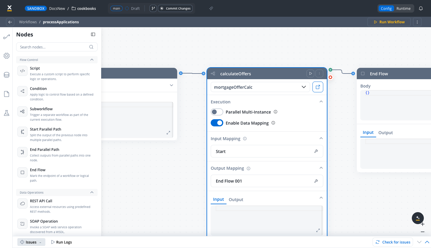
When data mapping is off, the node keeps its original behavior: the Input and read-only Output JSON fields described above. Turning Enable data mapping on replaces those with the mappers below.
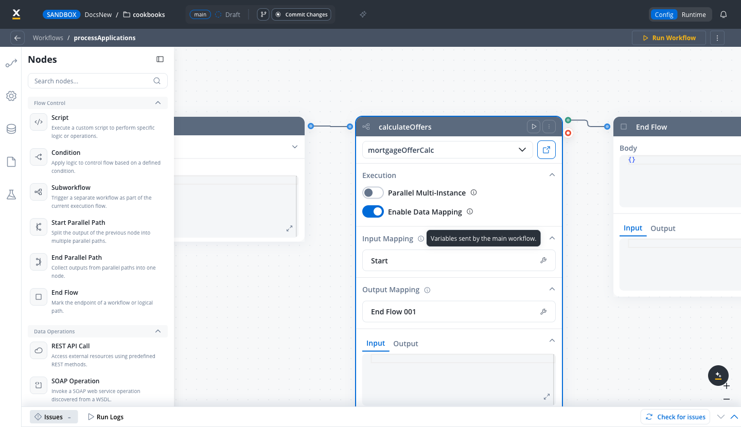
Output mapping applies only to synchronous subworkflows. If the subworkflow runs asynchronously, the parent does not wait for a result, so the Output mapping block is hidden.
1
Open the mapper
Click the edit icon on the Start row (input) or on an end-node row (output).
2
Map fields between the two data models
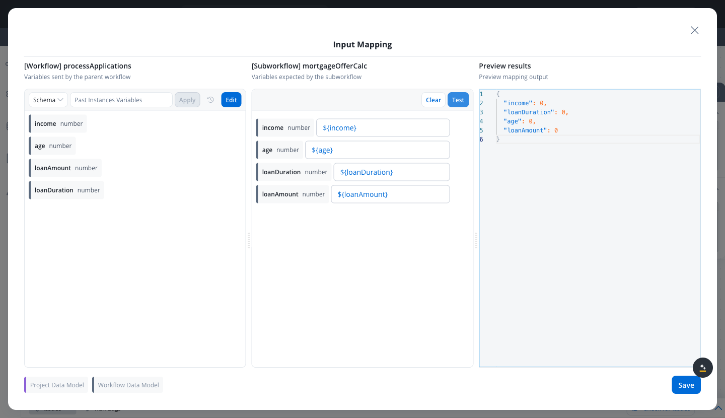
The modal shows the source data model on the left and the target data model in the middle. Each side is color-coded: Project Data Model and Workflow Data Model. Draw the field-to-field mappings, or define static values and expression scripts where a direct field match does not exist.
3
Test the mapping
Click Test to run the current mappings and preview the produced payload in the read-only results panel on the right. Any mapping errors are highlighted so you can correct them before saving.
4
Apply values from a past run (optional)
To test against real data, pick a previous workflow instance from Past Instances Variables and click Apply to load that instance’s values as the source example. Use the reset control to return to the default example values.
5
Save
Click Save to store the mapping on the node. In committed or upper environments the modal is read-only and shows Close instead.
Parallel multi-instance
SaaS · 5.12Available on SaaS with FlowX.AI 5.12. This feature is live on managed (SaaS) deployments now. Self-hosted deployments will receive it with the next LTS release family.
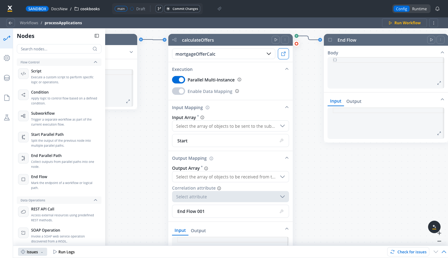
Turning Parallel Multi-Instance on also turns Enable Data Mapping on and locks it there, because each array element has to be mapped into the child workflow individually. The data mapping mappers stay available and work the same way.
Only array attributes from the workflow data model can be selected, and both arrays must be arrays of objects. If a dropdown offers nothing, the workflow data model has no array attributes to choose from.
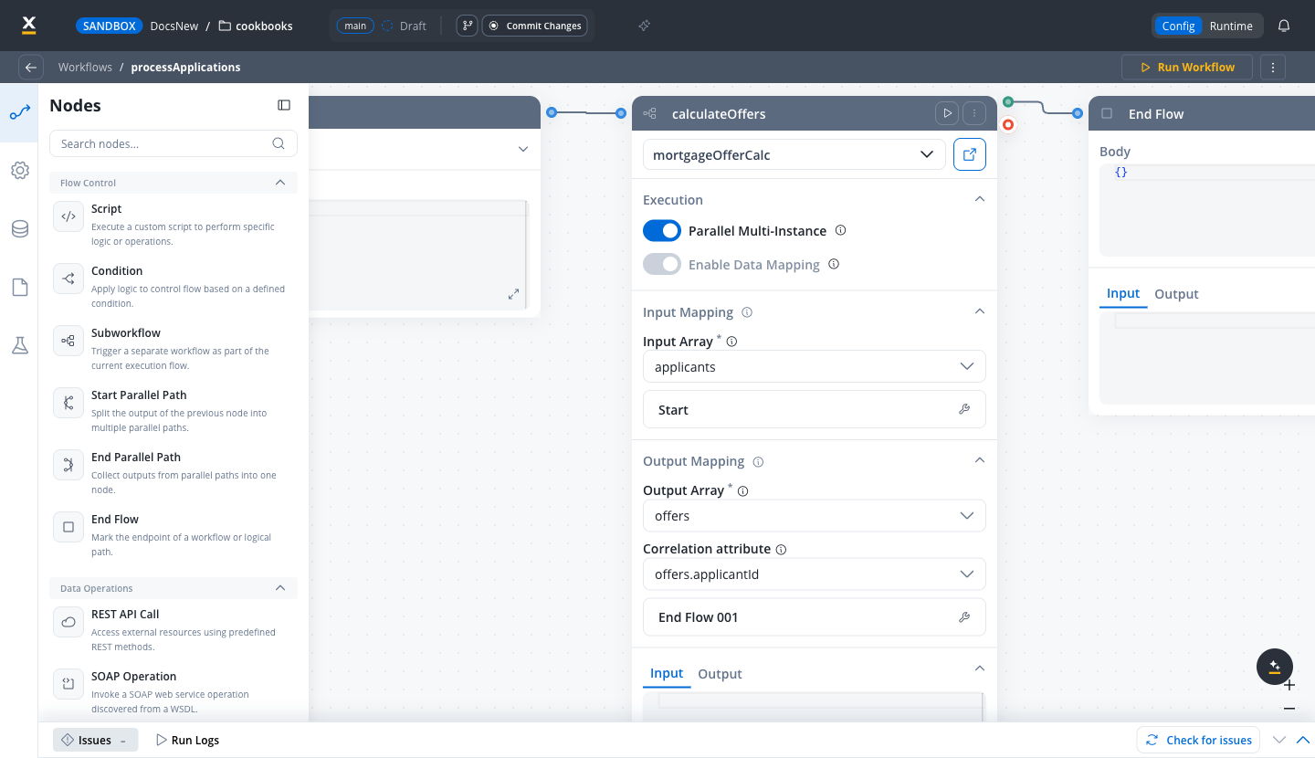
- A result whose correlation value matches an existing element of the output array updates that element.
- A result that matches no element is appended.
- With no correlation attribute set, every result is appended.
Parallel multi-instance is not the same as parallel branches. Start Parallel and End Parallel nodes run several different branches of one workflow at the same time. Parallel multi-instance runs one subworkflow many times, once per element of an array. Use parallel branches for different work in parallel, and multi-instance for the same work over a collection.
Execution logic and error handling
- Parent workflow waits for subworkflow completion before proceeding.
- If the subworkflow fails, the parent workflow halts at this node. On SaaS (5.12), connecting the node’s failure exit routes the failure down its own branch instead. See Routing a subworkflow failure.
- Subworkflow output is available to downstream nodes via the response key.
- Logs include workflow name, instance ID, and node statuses for both parent and subworkflow.
Subworkflow runs are recorded in workflow instance history for traceability.
Routing a subworkflow failure
SaaS · 5.12Available on SaaS with FlowX.AI 5.12. This feature is live on managed (SaaS) deployments now. Self-hosted deployments will receive it with the next LTS release family.
On the failure branch, the node writes a fixed
subWorkflowError key, separate from its response key:
The failure exit covers the node’s own mapping. A subworkflow that fails inside itself still cascades to the parent, whether or not the failure exit is connected.A manual single-node run also reports the error to you rather than following the branch.
Console logging, navigation, and read-only mode
- Console shows input/output, workflow name, and instance ID for each subworkflow run.
- Open subworkflow in a new tab for debugging from the console.
- Breadcrumbs enable navigation between parent and subworkflow details.
- In committed/upper environments, subworkflow configuration is read-only and node runs are disabled (preview/open only).
Subworkflow instances are logged in history, and you can navigate between parent and child workflow runs for comprehensive debugging.
Use case: CRM Data Retrieval with subworkflows
Suppose you need to retrieve CRM details in a subworkflow and use the output for further actions in the parent workflow.1
Create the Subworkflow
Design a workflow that connects to your CRM system, fetches user details, and outputs the data in a structured JSON format.
2
Add a Subworkflow Node in the Parent Workflow
In your main workflow, add a Subworkflow Node and select the CRM retrieval workflow. Map any required input parameters.
3
Use Subworkflow Output in Parent Workflow
Downstream nodes in the parent workflow can reference the subworkflow’s output using the defined
responseKey.4
Monitor and Debug
Use the console to view input/output data, workflow names, and instance IDs. Open subworkflow runs in new tabs for detailed debugging.
This modular approach allows you to build scalable, maintainable integrations by composing workflows from reusable building blocks.
End node
The End node signifies the termination of a workflow’s execution. It collects the final output and completes the workflow process.- Receives input in JSON format from the previous node.
- Output represents the final data model of the workflow.
- Multiple End nodes are allowed for different execution paths.
If the node’s output doesn’t meet mandatory requirements, it will be flagged as an error to ensure all necessary data is included. Output parameters declared in the workflow’s output schema are a runtime contract: when any of them resolves to no value, the run fails with
The mandatory output parameters of the <workflow> workflow are missing at runtime - see the error glossary.